
Home›Forums›Members’ Builds and Rides›VB – VC – VH – VK – VL›VB LSA Commodore build
This topic contains 380 replies, has 16 voices, and was last updated by ![]() Judge1 Frazer 2 years, 6 months ago.
Judge1 Frazer 2 years, 6 months ago.
-
AuthorPosts
-
October 30, 2019 at 4:20 pm #30380

Judge1 FrazerParticipant- new zealand
- 1983 VB LSA MG9 6060 6 speed
View build HERE
Posts: 775
It does seem a lot. Just trying to imagine that, so it would basically make the bottom of the front K member that much lower assuming the body of the car is at the same height right? That would make it pretty bloody low, less than 100mm which is legal min-height here in Oz I am guessing?
Hey Gary the way I see it, it would not change here the lower arms are still pointing down so all geometry stays the same I have coil overs in the front so ride height is sorted just some height adjustment I would lose in nz it’s a 100mm to the chassis, they have done this for years with 350 Chevy’s
October 30, 2019 at 8:38 pm #30382Geometry and bump steer changes. Ian can explain this at a greater depth.
Dropping it that much create issues with rack, headers, etc.
To gain the 48mm clearance under the car you would then have to raise the suspension.
October 31, 2019 at 11:21 am #30396
VRSenator065Participant- Adelaide SA
- VR Senator LSx454 1960 Kombi (project) 1921 Nash Hot Rod (future project)
View build HERE
Posts: 5 777Hey not being critical, at the end of the day it’s your car! And there is a def difference from oz to NZ, and actually even state to state in Oz. Here in SA, it is no part of the car can be lower than 100mm. On mine, the critical area was the bottom of the headers clearance ro the ground. Thank goodness for adjustable coil overs
 October 31, 2019 at 4:17 pm #30404
Judge1 FrazerParticipant- new zealand
- 1983 VB LSA MG9 6060 6 speed
View build HERE
Posts: 775Shit even the exhaust half the car here would be illegal
October 31, 2019 at 4:22 pm #30405
Judge1 FrazerParticipant- new zealand
- 1983 VB LSA MG9 6060 6 speed
View build HERE
Posts: 775The LCA mounts go down with the subframe, ditto on the rack mounts, all it really means is if you want the same static ride height you lose 50mm travel from the shocks. Holden screwed the pooch on bump steer anyway, eventually if you lower it too much you’ll drop the roll centres and it’ll handle like a pileOshit.. (#1 reason for the BMW build)
What Ian wrote on page seven on the bump steer and LCA
November 2, 2019 at 7:00 pm #30420
Judge1 FrazerParticipant- new zealand
- 1983 VB LSA MG9 6060 6 speed
View build HERE
Posts: 775photo’s from last weekend
Alternator
 20191027_150359 by Frazer Russell[/url], on Flickr
Starter, Flywheel, clutch
 20191027_150416 by Frazer Russell[/url], on Flickr
Bell-housing Modified
 20191027_150452 by Frazer Russell[/url], on Flickr
Mount Cut off from K Frame
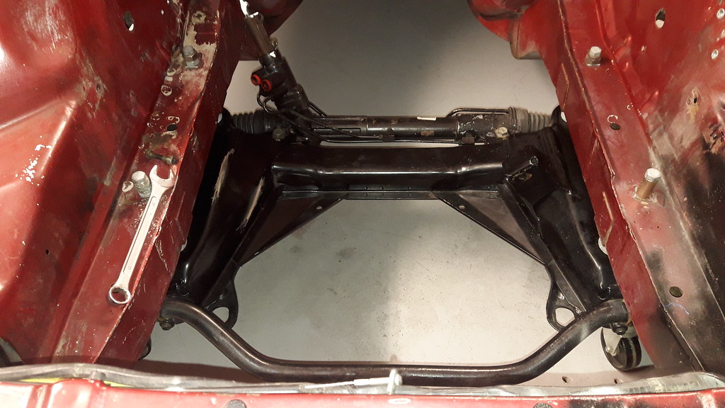 20191027_202819 by Frazer Russell[/url], on Flickr
New engine mount plate
 20191102_200946 by Frazer Russell[/url], on Flickr
with alternator installed new belt sorted
 20191102_202238 by Frazer Russell[/url], on Flickr
mount plate install just need to build rest of mounts
 20191102_203028 by Frazer Russell[/url], on Flickr
-
This reply was modified 4 years, 5 months ago by
 Judge1 Frazer.
November 4, 2019 at 11:33 am #30431
VRSenator065Participant- Adelaide SA
- VR Senator LSx454 1960 Kombi (project) 1921 Nash Hot Rod (future project)
View build HERE
Posts: 5 777Nice!
December 24, 2019 at 5:00 pm #30871
Judge1 FrazerParticipant- new zealand
- 1983 VB LSA MG9 6060 6 speed
View build HERE
Posts: 775well have had play with mounts got part of them sorted just have to set engine and box in the right place have taken both mounts of the x member , modified the angle braces to have a bit more clearance for oil pan
also had a L plate welded to the A/c Bracket and built up on the threaded parts just need to get it in the mill to start shaping it
Got the larger pulley on the crank for the blower and sorted a belt for it, forgot blower was not bolted down d’oh
found a manual rake aswell
 20191201_143834 by Frazer Russell[/url], on Flickr
 20191221_172159 by Frazer Russell[/url], on Flickr
 20191222_172859 by Frazer Russell[/url], on Flickr
 20191121_210003 by Frazer Russell[/url], on Flickr
 20191224_171454 by Frazer Russell[/url], on Flickr
 20191221_172226 by Frazer Russell[/url], on Flickr
 20191213_184545 by Frazer Russell[/url], on Flickr
-
This reply was modified 4 years, 4 months ago by Judge1 Frazer.
-
This reply was modified 4 years, 4 months ago by Judge1 Frazer.
December 24, 2019 at 5:42 pm #30874Good wrap on the Blower pulley, engine mounts aren’t going anywhere!
December 24, 2019 at 5:55 pm #30875
Judge1 FrazerParticipant- new zealand
- 1983 VB LSA MG9 6060 6 speed
View build HERE
Posts: 775Good wrap on the Blower pulley, engine mounts aren’t going anywhere!
yip I like not changing top pulley should not slip, your right Ian it’s not being built to just pussy foot around
December 24, 2019 at 6:05 pm #308768pk belt? If so not a chance if it slipping, are you spacing the subframe down for bonnet clearance?
December 24, 2019 at 7:40 pm #30877
Judge1 FrazerParticipant- new zealand
- 1983 VB LSA MG9 6060 6 speed
View build HERE
Posts: 7758pk belt? If so not a chance if it slipping, are you spacing the subframe down for bonnet clearance?
Yes 8pk belt and yes on the spacers have not put pictures up as I want to see it all done first and have it back on all four wheel with coil overs adjusted to suit , my engineer/fabricator is making the brackets for the brakes as I have not got the gear or skill to make them it’s a radial mount caliper and they are brakes don’t want them falling off
-
This reply was modified 4 years, 4 months ago by Judge1 Frazer.
December 24, 2019 at 7:40 pm #30878
Judge1 FrazerParticipant- new zealand
- 1983 VB LSA MG9 6060 6 speed
View build HERE
Posts: 775Hey Ian have I got this right for engine placement centre of rails in bay parallel/square off the front level left to right and about 3 degrees back ,I have set this up and I’ll have to slightly modify the hand brake bulge as the gearbox is a bit longer than factory ones , between gear box and diff is not a straight line maybe 15-20mm the universals should compensate for that right (one Piece )
December 24, 2019 at 8:13 pm #30880Sounds good, you’ll need to measure the angle on the diff flange then set the same angle on the trans output, 4 degrees on both is about the maximum, so you mean 10 to 15mm off the centre line left/right? If so yeah that’s fine. You could mount the engine off centre if it helps with steering clearence, many stock cars aren’t centred.
December 24, 2019 at 8:42 pm #30881
Judge1 FrazerParticipant- new zealand
- 1983 VB LSA MG9 6060 6 speed
View build HERE
Posts: 775Sounds good, you’ll need to measure the angle on the diff flange then set the same angle on the trans output, 4 degrees on both is about the maximum, so you mean 10 to 15mm off the centre line left/right? If so yeah that’s fine. You could mount the engine off centre if it helps with steering clearence, many stock cars aren’t centred.
yip centre line 15-20mm, as for pinion angle I have the adjustable top diff arms so that not an issue , setting of centre would move closer the handbrake
December 24, 2019 at 11:15 pm #30882Like most modified cars there will probably only be one sweet spot where it’ll be all good, hold off on finish welding the mounts till you’re 100% happy it ALL lines up how you want it!
December 25, 2019 at 7:16 am #30884
Judge1 FrazerParticipant- new zealand
- 1983 VB LSA MG9 6060 6 speed
View build HERE
Posts: 775Like most modified cars there will probably only be one sweet spot where it’ll be all good, hold off on finish welding the mounts till you’re 100% happy it ALL lines up how you want it!
that’s why they are tacked plus for engineering I need them to be welded by someone with a welding ticket
but as all ways thanks for the tips and info marry Christmas
 Santa never brought me anything this year
-
This reply was modified 4 years, 3 months ago by Judge1 Frazer.
December 30, 2019 at 3:51 am #30899
Judge1 FrazerParticipant- new zealand
- 1983 VB LSA MG9 6060 6 speed
View build HERE
Posts: 775Have been busy with mounts all tacked used some C-A-D as normal had it sitting nicely using a plumb bob levelled down off the sill sides then from the gear box, diff and crank , squared a line to the front adjusted motor and box to suit, diff and gear box is about 10mm offset but wanted more clearance for air con so move motor and box 10mm to passengers side diff will be fine as building a 9″ so can sit it where I need it , will have to modify the hand brake bulge
have a 10mm temporary spacer between the x-member and oil pan notched the angle bits on the x-member for oil pan clearance made some card board templates for mounts then made them out of 50x50x5mm angle welded together (had no Box section to make them out of ) a lot of cutting and grinding but got there, just got to do the gearbox mount
Also motor fits under bonnet

 20191227_183624 by Frazer Russell[/url], on Flickr
 20191227_170622 by Frazer Russell[/url], on Flickr
 20191228_142531 by Frazer Russell[/url], on Flickr
 20191228_142516 by Frazer Russell[/url], on Flickr
 20191228_192019 by Frazer Russell[/url], on Flickr
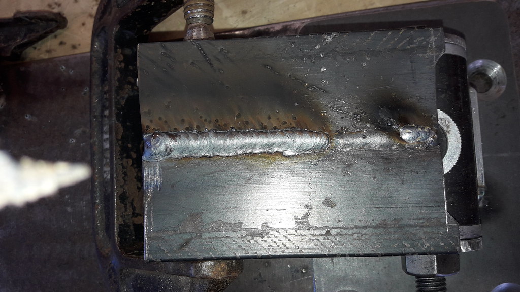 20191229_142701 by Frazer Russell[/url], on Flickr
 20191229_184446 by Frazer Russell[/url], on Flickr
 20191229_184502 by Frazer Russell[/url], on Flickr
-
This reply was modified 4 years, 3 months ago by Judge1 Frazer.
-
This reply was modified 4 years, 3 months ago by Judge1 Frazer.
-
This reply was modified 4 years, 3 months ago by Judge1 Frazer.
December 30, 2019 at 3:56 am #30902
Judge1 FrazerParticipant- new zealand
- 1983 VB LSA MG9 6060 6 speed
View build HERE
Posts: 775Got the aircon bracket ready for milling
 20191227_214959 by Frazer Russell[/url], on Flickr
 20191227_220500 by Frazer Russell[/url], on FlickrDecember 30, 2019 at 9:49 pm #30911
VRSenator065Participant- Adelaide SA
- VR Senator LSx454 1960 Kombi (project) 1921 Nash Hot Rod (future project)
View build HERE
Posts: 5 777Love this build mate. Seriously unless you have done one you don’t understand the time effort and thought that goes into it. Top work, going to be a weapon. Very thoughtful build.
-
AuthorPosts
You must be logged in to reply to this topic.
